China UV Curing LED Module Supplier: TOPLITE's Matrix Optics
5 min read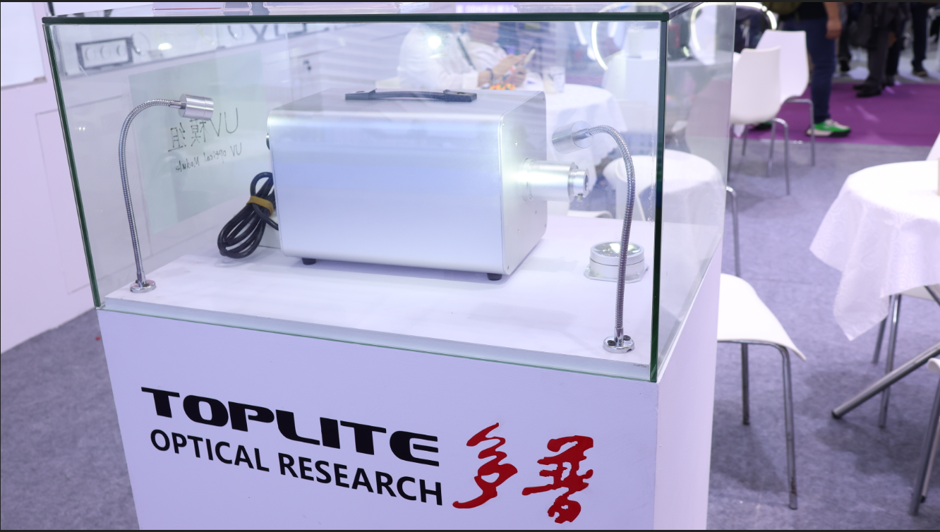
Overview: Meeting the High-Density Light Condensing Challenge
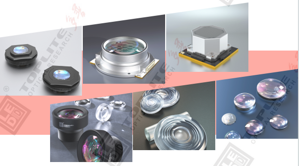
For manufacturers searching for a China industrial UV curing LED module supplier, one of the most persistent engineering challenges is achieving high-density light condensing with consistent spot uniformity. Standard optical setups often struggle to concentrate multiple LED sources into a small target area while keeping beam characteristics controllable. This is the exact pain point that TOPLITE, a supplier of UV LED matrix optical lens assemblies, optical modules, and collimated optical path configurations, has positioned itself to address. As an optical component and module supplier for UV LED industrial applications, TOPLITE focuses on curing, exposure, and photolithography scenarios where light intensity, uniformity, and controllability directly determine process outcomes.
TOPLITE's Patented Multi-Layer Fly-Eye Lens Matrix Design
At the core of TOPLITE's technology platform is a multi-layer optical fly-eye lens matrix condensing design, which is protected by invention patents in China, the United States, and Europe. This proprietary R&D supports configurations with up to 19 high-power UV LEDs, and optical parameters such as uniformity, beam angle, and wavelength can be customized for specific industrial requirements.
The value proposition is straightforward: by focusing LED matrix light into a relatively small area, the design delivers ultra-high luminous density and high-energy output. Optional homogenizing collimating components can be paired with the condensing lens to produce a uniform light spot, which directly addresses non-uniform illumination issues common in curing and exposure processes.
Key Technical Metrics
TOPLITE's matrix optical system supports the following technical specifications:
- LED quantity supported: up to 19 LEDs
- Supported LED package sizes: 3030 / 3535 / 5050 or custom dimensions
- LED wavelength options: 365 nm / 385 nm / 395 nm / 405 nm or customized wavelengths
- Optical output surface dimensions: Φ42 mm
- Focal length (F): 29 mm (varies by model)
- Focal point (G): 8 mm (shape and value vary depending on the LES of the LED chip)
- Beam angle: 2θ1/2 30° (varies by model)
- Matrix power range: 57 W to 260 W, based on single LED chip power multiplied by LED quantity
- External dimension: L57 mm × W57 mm × H33.6 mm
These parameters support both single-wavelength and multi-wavelength UV LED configurations, giving engineers flexibility when matching optical output to specific process requirements.
If you want to learn more about related optics knowledge, visit the following URL: https://youtu.be/U6nGQ2g9Y0E to get more related information.
Product Lineup: From Lens Assemblies to Collimated Optical Paths
TOPLITE offers four primary products built around the same fly-eye lens matrix condensing platform.
MATGOBO190UV LED Matrix Optical Lens Assembly
This condenser lens assembly is designed specifically for UV LED matrix light focusing in high-density condensing applications. It concentrates light emitted from an LED matrix into a relatively small area in space, delivering ultra-high luminous density and high-energy output. The assembly supports up to 19 single-wavelength or multi-wavelength high-power UV LEDs, enabling matrix power from 57 W to 260 W. Pairing it with a homogenizing collimating optical component produces a uniform light spot, while uniformity, beam angle, and wavelength remain customizable to match diverse industrial specifications.
MATGOBO190UV LED Matrix Optical Module
Building on the same condensing principle, this integrated module combines the fly-eye lens design directly with UV LED mounting, reducing system integration effort for curing, exposure, and photolithography equipment. It accepts 3030, 3535, 5050, or custom LED packages, and supports mixed UV wavelengths within the same module for tailored spectral output. The module shares the same technical highlights as the lens assembly, including the Φ42 mm optical output surface, 57 W–260 W matrix power range, and L57 mm × W57 mm × H33.6 mm external dimension.
High-Efficiency Collimated Optical Path
For applications requiring longer working distances, TOPLITE provides customizable collimated optical path configurations that combine the UV LED module with movable zoom lenses:
- MATGOBO190UV-125 with 209±20 mm movable zoom lens: Delivers a half-angle of 1.5° with a φ125 mm exit aperture. At a working distance of 1 m, radiant flux exceeds 910 mW over a 50 × 50 mm working plane; at 2 m, flux exceeds 230 mW over a 120 × 120 mm plane.
- MATGOBO190UV-125DF80 with 289±20 mm movable zoom lens: Also delivers a half-angle of 1.5° with a φ125 mm exit aperture, but with a longer adjustable optical path. At 1 m working distance, radiant flux exceeds 480 mW over a 65 × 65 mm plane; at 2 m, it exceeds 120 mW over a 120 × 120 mm plane.
Both configurations use 365 nm LED wavelength, which aligns with common UV curing and exposure process requirements, and both include uniformity curve graphs along with UV module plus optical fiber path schematics for deployment reference.
Reference Test Data and Performance Validation
TOPLITE provides reference test data using a specified LED model, MATGOBO190UV-D8, as the measurement baseline. Under this configuration, the system uses a 3535 LED package at 365 nm wavelength, driven at 1.5 A × 2 channels, producing 110 W power and 53 W/cm² radiant flux. The focal point (G) measures 8 mm, the focal length (F) is 29 ± 2 mm, and the beam angle (2θ1/2) is 30°.
Importantly, TOPLITE notes that this test result corresponds to the thermal solution matched specifically with TOPLITE's assembly, and that actual values depend on several variables: the selected LED chips, packaging process, SMD placement position accuracy, heat dissipation, and assembly precision. This transparency about the conditional nature of test data gives engineers a realistic framework for evaluating expected performance rather than presenting fixed guarantees.
Industry Applications
TOPLITE's optical solutions are adapted across three primary industrial segments:
- Curing: High-density UV condensing supports adhesive and coating curing processes, with the collimated optical path options extending projection over longer working distances for large workpieces.
- Exposure: Uniform light spot output, enabled by the homogenizing collimating components, supports exposure systems requiring defined working planes.
- Photolithography: Focused UV output, whether from the lens assembly, the integrated module, or the collimated optical path, supports lithography applications requiring controlled light distribution over specific target areas.
Conclusion
TOPLITE's approach to the UV LED matrix optical lens assembly, optical module, and collimated optical path market is built around a single, patent-protected engineering principle: the multi-layer optical fly-eye lens matrix condensing design. With patent coverage spanning China, the United States, and Europe, support for up to 19 LEDs, a matrix power range of 57 W to 260 W, and customizable parameters for uniformity, beam angle, and wavelength, the company addresses the specific condensing and uniformity challenges found in curing, exposure, and photolithography applications. For buyers evaluating a China-based UV LED module supplier, TOPLITE's transparent reference test data and modular product structure—spanning lens assemblies, integrated modules, and collimated optical paths—offer a clear basis for technical comparison against specific process requirements.
TOPLITE will be attending the 2026 LDI Show in the United States. We will be waiting for you at Booth #1509 and look forward to meeting you in Las Vegas from December 6–8, 2026! To see more of our Show videos, please visit the following link for more information:https://youtu.be/WQpPK4Mv2Dk

https://en.led3d.com/
TOPLITE
About Author