
Installation Procedure of E-Series Waterproof Connectors
2 min read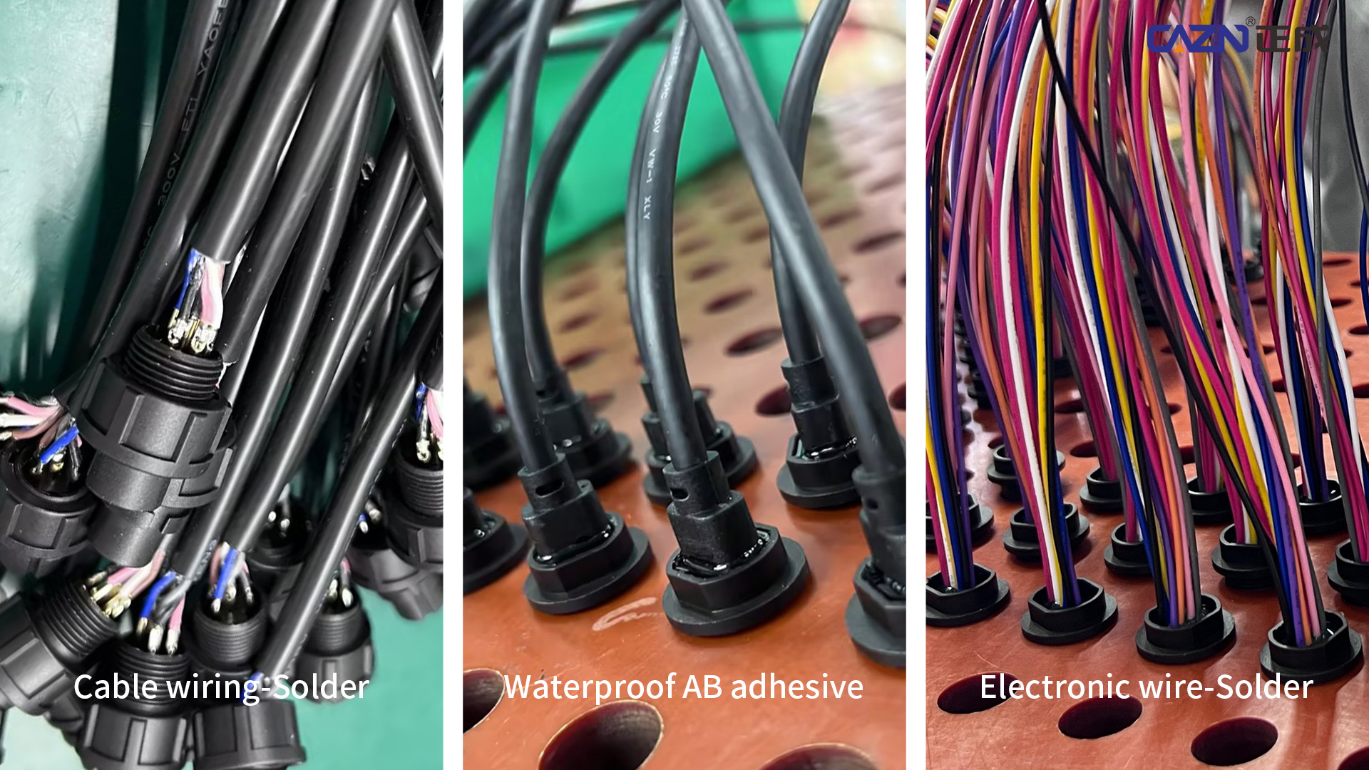
The installation process of E-series waterproof connectors is critical. Proper installation not only ensures stable signal and power transmission, but also guarantees true IP67-level waterproof and dustproof protection. Based on the characteristics of E-series products (such as E7, E10, E13, and E16), the standard installation and wiring process can be divided into two main sections: panel mounting and cable wiring termination.
Basic Installation Workflow for E-Series Cable Connectors (E10, E13, etc.)
1. Preparation and Disassembly
Loosen the rear locking nut or outer housing of the connector.Sequentially remove internal components such as the waterproof rubber insert and compression nut.Thread the cable through the rear cap and waterproof sealing insert.
2. Wiring Connection (Soldering or Screw Locking)
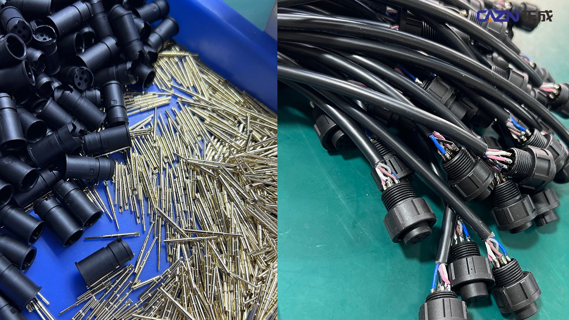
Solder-type (PCB/pin style):Strip the insulation from the wire.Solder the wire to the corresponding pin (male connector) or socket (female connector) inside the connector.Ensure no cold solder joints and avoid excessive solder that may cause short circuits.
Screw-lock type:Use a screwdriver to firmly secure the wire to the terminal.Ensure tight and stable electrical contact.
Quick-install type (some E16 push-lock versions):Lift the locking actuator.Directly insert the cable into the contact terminal until properly seated.
3. Sealing and Assembly (Most Critical Step)
-
Place the wired internal core back into the connector housing.
-
Adjust the waterproof rubber insert to ensure it tightly wraps around the cable jacket.
-
Tighten the rear locking nut. This step compresses the sealing insert, causing it to deform and firmly grip the cable, forming the first waterproof barrier.
4. Mating and Locking
Connect the plug and socket together.
Threaded types (E7 / E10 / E13):Rotate the coupling nut until fully tightened.
Push-pull / snap-lock type (E16):Insert until a “click” sound is heard, confirming secure locking.
Installation Characteristics of Different E-Series Models
The E-series includes multiple sizes and connection structures. Installation details vary slightly depending on the model:
| Model | Thread Specification | Connection Type | Installation Features & Applications |
|---|---|---|---|
| E7 Series | 7/16"-28UNS | Thread / Snap-lock | Compact design. Suitable for space-limited devices such as small sensors. Requires careful handling due to limited working space. |
| E10 Series | 5/8"-27UNS | Thread / Snap-lock | High versatility. Commonly used in Type-C power or data interfaces, balancing size and pin capacity (2–12 pins). |
| E13 Series | 13/16"-28UNS | Thread / Snap-lock | Designed for multi-core complex wiring. Supports up to 18 pins. Widely used for RJ45, HDMI, USB data transmission. Requires larger panel cut-out. |
| E16 Series | 1"-20UNEF | Quick push-pull lock | High-efficiency connection. No thread rotation required—simply push to lock, greatly improving installation and maintenance efficiency. Supports up to 22 pins. |
Key Principle of E-Series Connector Installation
The core of E-series connector installation is:“Internal secure termination + external locking sealing.”
As long as the rear waterproof insert is properly compressed by the locking nut, and the mating interface is fully locked via threading or snap-fit mechanism, the connector can achieve its optimal IP67 protection performance.
https://www.cazn.com/
Shenzhen CAZN Electronic Co., Ltd.
About Author
