Motor stator cable tie machine: Precision Binding Automation for High-Performance Motor Manufacturing
2 min read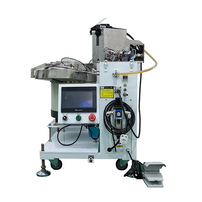
In modern electric motor manufacturing, structural integrity and winding stability directly determine motor efficiency, vibration performance, and long-term reliability. As production speeds increase and quality tolerances tighten, manual bundling of stator windings is no longer sufficient to meet industrial-grade consistency requirements.
This is where the Motor stator cable tie machine becomes a critical automation asset. It is not simply a fastening device—it is a precision control system designed to ensure consistent winding compression, uniform cable positioning, and repeatable binding force across high-volume stator production lines.
For industries producing traction motors, industrial servo motors, EV drive motors, and high-efficiency compressors, cable tie automation has become a core step in stator assembly quality control.
1. Functional Role of a Motor Stator Cable Tie Machine in Motor Assembly
During stator assembly, copper windings are subjected to mechanical stress, thermal expansion, and electromagnetic vibration during operation. Without controlled binding, the winding structure can shift, leading to:
-
Uneven air gaps in the motor core
-
Increased electromagnetic losses
-
Localized overheating due to insulation stress
-
Reduced motor lifespan under high-speed rotation
The Motor stator cable tie machine ensures:
-
Uniform radial compression of winding bundles
-
Fixed positioning of cable groups before impregnation
-
Controlled tension distribution across stator slots
-
Repeatable binding force for mass production consistency
Typical industrial performance targets include:
-
Cable tie tension range: 50–300 N adjustable depending on stator size
-
Binding cycle time: 2–8 seconds per tie point
-
Positioning accuracy: ±0.2–0.5 mm alignment tolerance
-
Compatibility range: stator outer diameter 80–600 mm
This ensures that each stator entering varnish impregnation or final assembly maintains identical structural stability.
2. Cable Tension Control: The Core Engineering Parameter
One of the most critical functions of a Motor stator cable tie machine is precise tension control. Unlike manual binding, which varies significantly between operators (±20–40% inconsistency), automated systems maintain tight control loops.
Key tension system characteristics:
-
Closed-loop servo motor control
-
Real-time tension feedback sensors
-
Digital adjustment resolution: ±1–2 N
-
Over-tension protection threshold programmable per motor type
Why tension matters:
-
Under-tension (<50 N equivalent in small stators) leads to winding vibration during operation
-
Over-tension (>300 N) risks insulation damage or copper deformation
-
Inconsistent tension creates electromagnetic imbalance in multi-phase motors
Advanced systems implement multi-stage tensioning logic:
-
Pre-tightening phase (cable positioning)
-
Main tightening phase (force application)
-
Final stabilization phase (compensation and lock)
This ensures uniform mechanical compression without localized stress peaks.
3. Automation Precision in Stator Geometry Adaptation
Modern motor production involves a wide range of stator geometries:
-
Inner diameter variations: 30 mm to 400 mm
-
Slot counts: 12 to 96 slots depending on motor type
-
Wire bundle thickness variability: 1–15 mm equivalent group size
A high-performance Motor stator cable tie machine must adapt dynamically to these variations.
Key adaptive technologies include:
-
CNC-controlled radial positioning system
-
Auto-detection of stator outer diameter via laser sensors
-
Programmable tie-point mapping per stator model
-
Quick-change fixture systems for different production lines
Positioning accuracy benchmarks:
-
Radial positioning error: ≤0.3 mm
-
Angular alignment error: ≤0.5°
-
Repeatability over 10,000 cycles: deviation <1%
This ensures compatibility across EV motors, industrial servo motors, and compressor motor lines without mechanical retooling delays.
4. Production Speed vs Quality Stability Trade-off
In high-volume motor manufacturing, cycle time directly impacts cost efficiency. However, increasing speed often introduces instability in winding compression and tie accuracy.
Typical production benchmarks:
-
Standard cycle time: 3–6 seconds per binding point
-
High-speed configuration: up to 10–15 stators/min depending on complexity
-
Continuous operation: 20–22 hours/day industrial duty cycle
Key engineering challenge:
-
Maintaining tension consistency at high speed
-
Avoiding wire displacement during rapid fixture movement
-
Ensuring knot reliability under vibration conditions
To solve this, advanced machines use:
-
Dual-axis synchronized servo systems
-
Anti-backlash feeding mechanisms for nylon cable ties
-
Predictive motion control algorithms to reduce mechanical shock
This allows speed scaling without sacrificing binding integrity.
5. Nylon Cable Tie Behavior and Material Compatibility
The performance of a Motor stator cable tie machine is strongly influenced by the mechanical properties of nylon ties used in the process.
Key material characteristics:
-
Tensile strength: 80–220 N depending on tie grade
-
Operating temperature range: -40°C to +120°C
-
Moisture absorption impact: ±3–5% dimensional variation
-
Elastic recovery rate: <5% after tension locking
Industrial machines must compensate for:
-
Thermal expansion of nylon in high-temperature workshops
-
Batch variation in tie thickness (±0.05–0.1 mm tolerance)
-
Friction coefficient variation during feeding and locking
High-end systems integrate:
-
Automatic lubrication feeding channels
-
Anti-jam detection sensors (feed force monitoring)
-
Real-time tension recalibration for different tie batches
This ensures stable performance even under long production shifts.
6. Integration with Motor Manufacturing Lines
A Motor stator cable tie machine is typically integrated into a larger stator production workflow:
-
Stator winding machine output
-
Cable bundling and pre-alignment station
-
Cable tie automation station
-
Varnish impregnation system
-
Baking and curing furnace
Integration requirements include:
-
PLC communication compatibility (Siemens, Omron, Mitsubishi systems)
-
Cycle synchronization with upstream winding line
-
Buffer station support for continuous flow production
-
Error feedback loop for upstream correction
Typical system synchronization tolerance:
-
Line speed mismatch: ≤5% allowable deviation
-
About Author